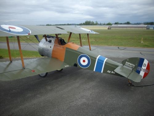
CMF Sopwith Camel Replica
The Museum’s Sopwith Camel is often on display in the Fraser Valley. There are several questions that are often asked when the Camel is on display;
Here are some interesting technical aspects of the Camel. Remember that in 1916 only 13 years had passed since the Wright Brothers flew a controllable aircraft. And the first international flight from France to Britain was as recent as 1909. For its day the Camel was as much a state-of-the-art fighting machine as the CF-18 is today.
In 1916, the Germans controlled the skies over the trenches, and the English developed three fighters to regain control of the air war. The best and most famous of these three designs was the Sopwith Camel. Small and lightweight, the Camel represented the latest in fighter design at the time. The Sopwith Camel shot down 1,294 enemy aircraft during World War I, more than any other Allied fighter. However, it was so difficult to fly that more men lost their lives while learning to fly it than using it in combat. A total of 5,490 Camels were built.
The Sopwith company rolled out the first Camel in December 1916. The Camel was a revolutionary machine in a number of respects. The plane’s twin Vickers machine guns were mounted side by side in front of the cockpit—a first for British fighters and a design feature that became standard on British fighters for nearly 20 years. Second, the pilot, engine, armament and controls were all crammed into a seven-foot space at the front of the airplane. This gave the plane a phenomenal performance, but it also made the plane very tricky to fly. Additionally, the plane’s wood and fabric construction and lack of protection for the fuel tank made the Camel (like most WWI aircraft) very susceptible to fire. Moreover, the poor state of pilot training during 1916-1917 meant that the average life expectancy of an English pilot was little more than two weeks.

The Camel is made of high-quality wood, covered with fabric.
The name “Camel” was derived from the hump-shaped cover over the machine guns. In order to combat Zeppelins, the Navy’s Camels were flown from barges towed behind destroyers, from platforms on the gun turrets of larger ships as well as from early aircraft carriers. A Camel 2F.1 successfully flew after being dropped from an airship, an experiment testing an airship’s ability to carry its own defensive aircraft.
The Why and How of Rotary Engines.
To try and answer the why and how of rotary engines is not easy ninety years after they were in widespread use.
First, a clarification of the terms ‘rotary’ and ‘radial’ as applied to aircraft engines. Both of these designs have the cylinders arranged around the crankcase in a radial manner, i.e. the centerline of the cylinders all intersect at the crankshaft.
The main difference is that with ‘rotary’ engines the cylinders rotate around the fixed crankshaft, while on the ‘radial’ engine, the cylinders are fixed and the crankshaft turns. In the first case the propeller is attached to the cylinders, while in the latter it is connected to the crankshaft.
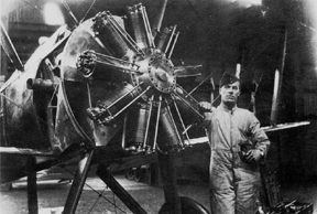
A rotary engine installed in a Camel.
The ‘Why’ of Rotary engines.
Why did engineers construct an engine that seems so illogical by today’s standards? Considering that powered flight had only begun a decade before WW1 and practical powered flight only in 1909 it becomes clear that a lot of inventive ideas were being tried at the time.
The first aircraft engines were adaptations of motor vehicle engines where weight was not a major consideration—liquid-cooled V-8 aircraft engines by Curtiss, and by Renault were heavy and unreliable. For the fighter aircraft designer it was imperative to have an engine with high power for the lowest possible weight. The Rotary engine was able to meet these demands and weighed 3 lb. per horsepower—a considerable improvement over inline engines.
The Rotary engine ran at low RPM (usually 1200 RPM) that resulted in large pulsations from each power stroke. One method of damping this out was to use a flywheel. However, in the Rotary the rotating cylinders and propeller acted as a flywheel, thus saving weight.
Another advantage of the Rotary design was that the cylinders were cooled by the passing airflow even when the aircraft was stationary. With the state of the development of engines at this time it was difficult to find metals that would not distort with the heat required for high power engines.
On the negative side, aircraft powered by the Rotary engine suffered considerably from the ‘gyroscopic effect’ of the large rotating mass. This effect caused the aircraft to yaw each time a change in attitude was made. On takeoff at low speed just raising the tail to gain flying speed would cause a swerve to the left. As the nose was raised to lift off the ground the aircraft would ‘kick’ to the right. Turns in flight created strong nose-up or nose-down forces resulting in the ability to turn extremely sharply to the right and very poorly to the left.
The Rotary suffered from poor fuel consumption due to the limited throttle capability, and very high oil consumption owing to the ‘total-loss’ oil system, i.e. the oil was pumped out of the cylinders during combustion and not returned to an oil reservoir.
The relatively light weight advantage of the engine was partially offset by the ‘windage’ of the cylinders. That is, as the engine turned, the cylinders created drag; a small factor at lower speeds, but an increasing penalty as speed increased. In effect, some of the engine power was being used to spin the engine against the resistance of the air.
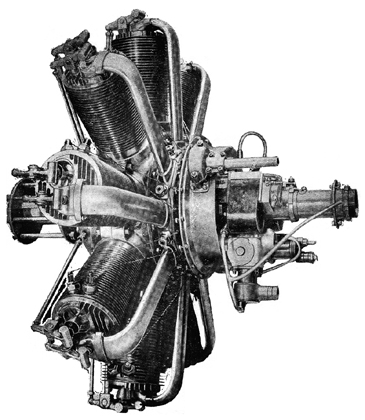
110 hp Clerget aircraft engine.
The ‘How’ of Rotary engines.
When it is realized that these engines have rotating cylinders, some technical questions come to mind. How was the fuel/air mixture delivered to the cylinders if they were constantly changing position? Also how was a spark sent to the spark plugs if these were also in motion? This description covers the Clerget engine, a typical WW1 Rotary engine, built by the thousands in France and Britain.
To start at the beginning of the fuel/air cycle we can look at the elementary carburetor that was located on the end of the crankshaft at the rear of the engine. An air intake pipe came in from each side of the engine cowl to the carburetor. A fuel line delivered fuel through a metering needle. The pilot’s throttle controlled an air valve and the fuel metering needle. A fine adjustment of this needle allowed control of the fuel to provide correct mixture at altitude. The fuel/air mixture then passed down the hollow crankshaft to the crankcase where it was thoroughly mixed by the rotating engine parts. It was then ducted from the crankcase through an external inlet manifold to the top of the cylinder. The burnt mixture was passed directly out of the cylinder to atmosphere with no ducting.
To ensure an adequate supply of fuel to the engine in all maneuvers the fuel from the fuselage-mounted tank was pressurized by an air pump. On some aircraft this was an engine-mounted pump, on others the pump was driven by a small propeller mounted on a wing strut just above the fuselage. (Note this on the CMF Camel on the right fuselage-to-wing strut above the cockpit). The pilot also had a cockpit mounted pump used when starting the engine.
The lubricating oil was also delivered through the crankshaft, a relatively easy task as the plumbing was easily attached to the interior of the fixed crankshaft. From here it was directed through drilled passageways to the various components that required lubrication.
A well known feature of Rotary engines was its use of castor oil. The reason is lost until we examine the lubrication system in detail. With the fuel and oil mixed together in the crankcase it was important that the fuel not dissolve the oil and ruin its lubricating qualities. The perfect choice was pharmaceutical-quality castor oil—it would stand the heat and centrifugal force, and its gum-forming tendency were irrelevant in a total-loss lubrication system. An unfortunate side effect was that pilots inhaled and swallowed a considerable amount of the oil during flight, leading to persistent diarrhea. This also accounts for the pilot’s use of a flowing white scarf—not for a dashing image, but to wipe goggles clear of the persistent oil mist flowing past the cockpit.
Now that we have fuel and oil flowing to the engine the third essential ingredient is a means of providing a spark for combustion. Typically, these engines used dual magnetos to provide a reliable source of ignition. The magnetos were mounted on the stationary rear casing of the engine. The spark was distributed to the cylinders via brushes that contacted a rotating distributor plate, then through brass wires to the spark plugs. Earlier engines, such as the Monosoupape, needed a pilot-operated switch to cut the ignition off to reduce engine power. However, the Clerget in the Camel had sufficient throttle authority that even though the ‘blipping’ switch was retained, it was rarely needed.
A variety of inlet and exhaust valve configurations were used on early engines. The Clerget had separate valves driven by push rods operated by a cam mechanism in the front of the engine. Valve springs were a major weakness, as material strength was often inadequate, resulting in frequent exhaust valve failures.
As with the Radial engine, most of the Rotary engines employed a master rod that was attached to the crankshaft. Around the periphery of the master rod were attached the auxiliary rods from the remaining cylinders. Pistons were initially made of cast iron, but later were made of aluminum alloy achieving a considerable weight saving.
The design of the cylinders went through a learning curve as material improvements were incorporated. The Le Rhone cylinders were made of steel with cast iron liners; the Clerget cylinders were nickel steel machined from a solid billet to a thickness of 3 mm. and featured integral cylinder heads. Overheating and distortion of these cylinders was a problem.
The later 150 hp Bentley B.R.1 (used on the Camel 2 F.1 operated by the Royal Navy) featured several improvements as designer W. O. Bentley had worked on Clerget engines; cylinders barrels were made from aluminum with shrunk-in liners; pistons were also aluminum; cylinder heads were removable; and the cylinders were able to be removed without dismantling the engine. The second Bentley engine, the B.R.2 was the most powerful Rotary engine of WW1, producing 235 hp with a power to weight ratio of 2 lbs/hp. This engine powered the Sopwith Snipe in which Major Barker won the Victoria Cross.
After WW1 the Rotary engine was abandoned, as greater power output meant larger diameter and weight leading to unacceptable gyroscopic forces. The Radial, Inline and Vee engines took over until the advent of the turbine engine less than 25 years later.
Click here for an animated example of a Rotary engine - Refer to "Gnome Rotary" on the second row.
“Why was the propeller not shot off when the pilot fired the guns?”