THE DEVELOPMENT OF INSTRUMENT FLIGHT TRAINERS
History
Why do we need devices to teach pilots how to fly in bad weather? For hundreds of years the cavalry galloping across the plains, or mariners in sailing ships never needed such things – why do we need them now?
When walking along a trail in a forest at night without any light we know which way is up by our inner-ear balance mechanism and the sensation of gravity. When a pilot is flying in good weather the horizon shows where ‘up’ is. However, when flying in poor visibility – rain, fog, snow, darkness – the balance mechanism of the inner ears becomes confused and the pilot will have no idea where ‘up’ really is. If the plane starts to turn gently the pilot will be unaware of this. He may notice that the compass is turning and the airspeed is increasing and will apply corrections. But without reference to the ground the corrections may lead to a spiral dive with tragic consequences.
The US Post Office established an airmail system after World War 1. This was expanded across the nation with lighted beacons for night flying. By 1927 the system was operated by private companies and then by the US Army until the high fatality rate shut down the system of flying by visual means.
Instruments were developed in the late 1920s that mimicked the horizon – known as the artificial horizon – regardless of the attitude of the aircraft. Thus a pilot could fly in adverse weather and still have a picture of the aircraft relative to the horizon. Aviation technical pioneers such as Elmer Sperry (artificial horizon and gyroscopic compass), Paul Kollsman (altimeter) and the Bell Telephone Co. (radio communication receiver), combined with the determination of James Doolittle, perfected the art of ‘blind flying’ as flying by reference to instruments was then known.
The ground-based Adcock antenna navigation system, known as the Radio Range became the standard in the 1930s. This transmitted a series of either the letter A in Morse code (. –) or N (– .) in each of four quadrants. The pilot would hear either of these letters over his headset, or would hear a constant hum when on course. This, combined with the voice radio, gave pilots the freedom to fly in all weather conditions or darkness.
Training Devices
However, aircraft and ground systems are no use unless there are trained pilots to use them. This is where the Link Trainer filled the void. In the safety of a building the pilot could be trained to fly a specific route at a specified altitude, then at the appropriate position start a descent to break out of cloud above the airport. The Link Trainer could be used in all weather conditions and at all times of the night and day making it a cost effective trainer.
In the late 1920’s Edwin Link learned to fly while working for his father who manufactured organs and pianos. Because of the economic depression at that time, flying lessons became too costly for him. Link got the idea to shorten the expensive flying lessons by learning rudimentary piloting skills using a ground aviation trainer. Drawing from his expertise in air-driven pianos and pipe organs, Link used organ parts and compressed air to build the first flight simulator.
In 1928, Link left his father’s organ building business to begin work on a ‘pilot trainer.’ He designed the trainer using suction through fabric bellows to cause motion. Organ bellows and a motor provided the means for the trainer, mounted on a pedestal, to pitch, roll, dive and climb as the student ‘flew’ it. In 1931 he received a patent on his ‘pilot maker’ training device.
Most of his first sales were to amusement parks. In the beginning there was very little interest by the flying community in Link’s trainer. Initially the Trainer was meant for instruction of visual flight, but in 1934, after a series of tragic accidents while flying the airmail, the Army Air Corps bought six Link Trainers to assist in training pilots to fly at night and in bad weather, relying on instruments.
The need for pilots with instrument training in World War 2 resulted, by the end of the war, in Link delivering 6271 Link Trainers to the Army and 1045 to the Navy. 35 foreign countries also used the Link Trainer. Although aviation cadets flew various trainer aircraft, virtually all took initial blind-flying instruction in the Link.
The Link Trainer holds a significant place in aviation history. It was the first true flight simulator, and provided safe training to hundreds of thousands of student pilots during the 1930s and 40s.
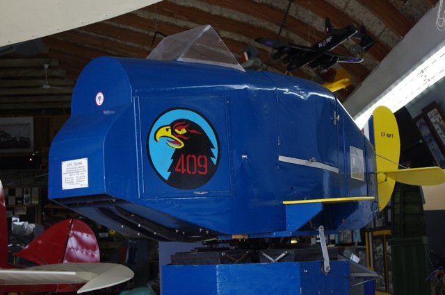
The Museum's Link Trainer on display in the hangar.
The Trainer had a long history and important training role with 513 New Westminster Air Cadet Squadron. The Air Cadet Squadron donated the Trainer to the Museum.
The Museum's Link Trainer was overhauled at CFB Comox by Flight Simulator Technical Personnel in 1971. To transport the Trainer to Comox for the rebuild it was moved across a large field and a road to the soccer field near the former Queens Park Arena to be loaded onto an RCAF Labrador helicopter. It was returned the same way. In 2011, Museum volunteers restored the Trainer to working condition.
Thanks to Robert Morrow, Training Officer for the Squadron from 1976-1979 for this history.
Operation of the Link Trainer
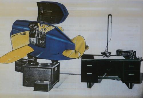
The miniature aeroplane is pivoted on a universal joint mounted on an octagonal turntable, which in turn is free to rotate in azimuth on a square base. Between the fuselage and the turntable are four supporting bellows, which are inflated or deflated by a vacuum turbine. Its valves are operated as the pupil moves the control column, and realistically recreates most of the sensations and feel of flying. The Model C of 1936 was able to rotate through 360 degrees, which allowed for a magnetic compass to be installed, while the various instruments were operated either mechanically or pneumatically. With further refinements along the way, the Link Trainer became a simple form of analogue computer, fitted with a full set of instruments to guide the pupil on an imaginary flight.
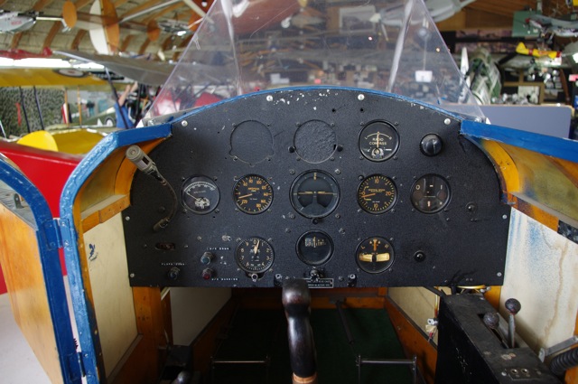
The Link Trainer's instrument panel. A hinged hood covered the cockpit when the trainer was in action.
The simulated course was automatically recorded and traced by the three-wheeled course plotter (the self-propelled and steerable ‘crab’) across a map on the instructor’s desk. A duplicated instrument panel was also present at the instructor’s station, electronically harmonised with those in the Trainer’s cockpit. By relating the position of the student’s aircraft to marks on the chart, the instructor was able to manually control the transmission of simulated radio beacon signals to the Trainer.
The instructor could create both calm and rough-air flying conditions. The Trainer would also initiate a stall when recorded airspeed and attitude fall outside pre-determined limits. It would then go into a very realistic spin, with the instruments performing normally for such conditions. A cross-country ‘flight’ of up to 200 miles was possible, during which the instructor was able to confront the pupil with most of the difficulties that could occur during a genuine flight.
Flight Training
The Harvard provides another link in the instrument-training curriculum of budding pilots. The Harvard Mark 4 was developed as an instrument trainer. After initial training in the Link, pilots would continue their training in the Harvard where the rear cockpit was fitted with a canvas hood that masked the outside world. The pilot would plan a trip, then board the aircraft and fly on instruments from the rear seat without seeing the ground until completing an instrument approach at the destination airport. The front seat pilot acted as the safety pilot.
Further development
After WW2 Link developed electronic training devices for the new generation of high-performance aircraft, and in the 1960s developed simulators for the space program, including the Apollo mission for moon landing.
Today multi-million dollar flight simulators ($20 million) are used for training crews for complex aircraft – airliners, transports and fighters. These trainers have sophisticated motion systems and visual displays that create such an authentic training environment that most pilots who use this training system do their first flight in a new type of aircraft with a load of passengers. We have come a long way since the days of the Link Trainer!
GAT-1
These trainers, the last generation of mechanical flight simulators that dominated the market from World War I until the 1960s, consist of a fibreglass cab mounted on a heavy base bearing the name ‘Singer’ just like the sewing machine. The Singer Corp. bought the design from the company of its inventor, Edwin Link, in the 1950s.
The gyroscope-controlled, six-degrees-of-freedom mechanical base of the GAT-1 is capable of throwing the tiny fibreglass cab of the GAT-1 through a 360-degree turn at any pitch up to 10 degrees at a touch of the controls, feeding the resulting information back to the instruments in the cab.

The cockpit of the GAT-1 is representative of modern training aircraft.
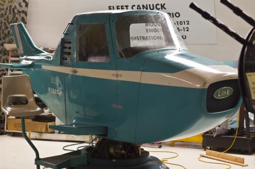
The GAT-1 flight simulator.
The Canadian connection
Before and during WW2, Britain had restrictions on buying war goods from non-Commonwealth countries. Link realized that business would only increase if he had a plant in Canada. He owned an island east of Gananoque, Ontario and frequently flew from Binghamton, NY in his amphibious plane to his cottage. As he always checked in with Customs and Immigration at Gananoque, he got to know the collector of Customs, Ken Mullins. One day he asked Mullins if he knew of a location where he could manufacture Link Trainers, and whom he could recommend as its manager. Mullins suggested Keith Taylor and in 1938, the first Link Trainer was built in what became known as the ‘Link Plant,’ later known as the ‘Cliffe Craft Boat Buildings’ and is now vacant. Over 5,000 Link Trainers were built in Gananoque and with over 200 employees it was one of the town’s most-important businesses.